
- Moving Probe Tester
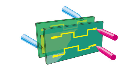
Special Moving Probes Conduct High Speed / High Accuracy Testing
to Detect Faults on both sides of the Board
Measurement System
Phase Difference Measurement (PDM)
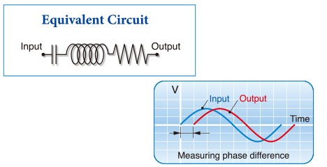
Phase Difference Measurement (PDM)
MicroCraft's independently developed testing method which exponentially speeds up both continuity/isolation tests. This method is most suitable for medium size production quantity.
Phase Difference Measurement (PDM) Unit
Phase Difference Measurement Unit (PDM) sends high frequency signal between the reference line (plane) and signal line to measure differences between these phases, which will cut down unnecessary isolation tests within the net. With fewer test points and test cycle compared to ordinary isolation test, the test speed have increased dramatically.
Kelvin Probe Optional
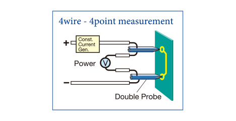
Precision Resistance Measurement Unit
A 4 wire, 4 points measurement method by Kelvin probe allows high accuracy testing by low resistance. Furthermore, measuring Buried Resistance and saving the measured values are also included.
Min. Resolution: 0.001 mΩ
Also can check probe contact error
| Range | Resolution | Measurable range | Current | Application |
| 0–4 mΩ | 0.001 mΩ | 0.4 mΩ–3 mΩ | 150 mA | Kelvin Probe |
| 0–40 mΩ | 0.01 mΩ | 2 mΩ–30 mΩ | 125 mA | Kelvin Probe |
| 0–400 mΩ | 0.1 mΩ | 30 mΩ–300 mΩ | 125 mA | Kelvin Probe |
| 0–4 Ω | 1 mΩ | 0.3 Ω–3 Ω | 125 mA | Kelvin Probe |
| 0–10 Ω | 2.5 mΩ | 0.5 Ω–8 Ω | 10 mA | |
| 0–100 Ω | 25 mΩ | 5 Ω–80 Ω | 10 mA | |
| 0–1000 Ω | 250 mΩ | 50 Ω–800 Ω | 2.5 mA | |
| 0–10 kΩ | 2.5 Ω | 500 Ω–8 kΩ | 0.25 mA | |
| 0–100 kΩ | 25 Ω | 5 kΩ–80 kΩ | 25 µA | Buried Resistance |
| 0–1 MΩ | 250 Ω | 50 kΩ–800 kΩ | 2.5 µA | Buried Resistance |
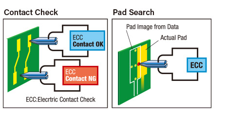
Contact Check in Isolation Test
In order to improve isolation test accuracy, this feature enables users to verify probes are correctly in contact with the pad prior to testing. This contact check function effectively assist the user during pad search.
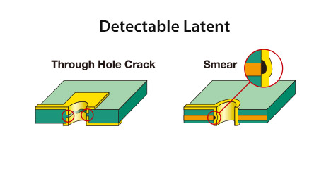
LATENT Test Optional
LATENT Test is a revolutionary quality assurance system that can predict and detect not only current errors in pattern inspection,
but also potential error locations that may become defects in the near future.
The optimum inspection mode can be selected according to the board specifications.
Low frequency analog measurement mode
Used for conductors formed on substrates with low thermal conductivity such as glass epoxy.
High-frequency analog measurement mode
Used for thin conductors formed on substrates with high thermal conductivity such as ceramic or aluminum.
Digital LATENT measurement mode
Used when you want to adjust the current or frequency applied to a conductor for measurement.
| Specifications | ANALOG LF | ANALOG HF | DIGITAL |
|---|---|---|---|
| Applicable board | Normal substrate |
Thin conductor |
Normal substrate |
| Conductor thickness | 15 µm–75 µm |
3 µm–40 µm |
15 µm–75 µm |
| Conductor width | 50 µm–250 µm |
10 µm–100 µm |
50 µm–250 µm |
| Maximum line resistance | 10 Ω |
10 Ω |
10 Ω |
| Detection signal | 2 kHz (2nd harmonic) |
450 kHz (intermodulation) |
Digital Signal Processing |
| Drive frequency | 1 kHz + DC |
1.46 MHz + 1.10 MHz + DC |
5 k–40 kHz Variable |
| Drive voltage (Max.) | 15 V |
5 V |
0–30 V Variable |
| Drive current (Max.) | 1.5 A |
400 mA |
0–1.5 A Variable |
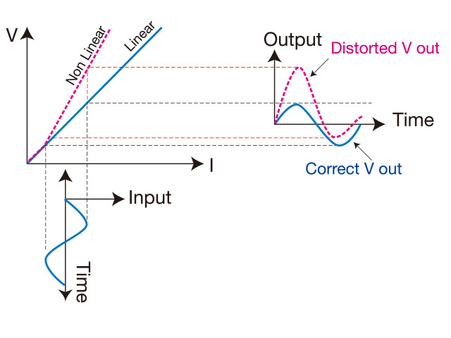
The pattern with “latent” or dormant defect, when applied with high current will induce temperature rise causing the output resistance to become nonlinear. This change shall be detected at high speed and accuracy and thus detect Latent defect.
HVS (High Voltage Stress Test) Optional
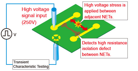
HVS (High Voltage Stress Test) is a measurement system that is capable of detecting high resistance isolation defect which was undetectable with Phase Difference Measurement (PDM). HVS is conducted by applying high voltage pulses between signal lines to detect high resistance defect. HVS similar to PDM, inspects each net once, thus achieves much faster test speed compared to ordinary isolation test by resistance measurement. This revolutionary testing method can be upgraded as an option to our EMMA series.
Spark detection function Optional
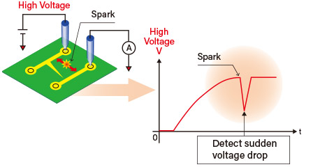
Generally, isolation tests guarantee isolation resistance by applying an inspection voltage between test nets and measuring the leakage current after a certain period of time has elapsed. In this case, impurities on the PCB, narrow gaps between patterns, etc., are destroyed by sparks generated by the inspection voltage, and are judged as good products. The spark detection function monitors the voltage from the start of inspection voltage application until it reaches the specified voltage, and if a sudden voltage drop or abnormal voltage rise due to sparks is detected, it can be processed as a spark error judgment.
Micro-Short Inspection
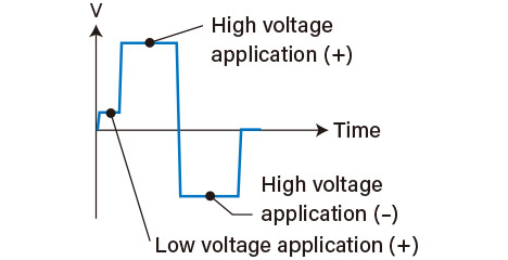
If a high voltage is suddenly applied during isolation testing, the micro shorts may burn out, and the carbonized residue from the burnout may react with moisture in the air or gases in the factory, resulting in high-resistance isolation defects that may recur after the testing is completed. Micro-short inspection first inspects at a low voltage of 30V or less before applying high voltage to prevent problems caused by burnout. In addition, high-resistance isolation defects between layers of a multilayer board may have the characteristics of semiconductors or capacitors, but by changing the polarity of the high voltage during the inspection, it is possible to detect these defects as well.
Hipot Test
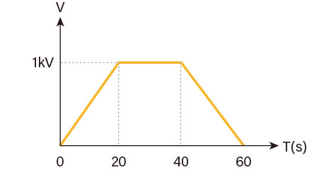
The hi-pot test is an option for measuring the withstand voltage characteristics of a board. A voltage is applied to the board for an extended period of time to test for leakage current. The test point creation software (TPG) allows the user to program the applied voltage and time, the determined current value, and multiple test points, and to test for various standards, such as gradually applying voltage from 0 to 1000V, maintaining 1000V for 20 seconds, and then gradually lowering the voltage to 0 V. The GPIB interface High-voltage testing equivalent to 1000V is also possible by connecting an external high-potentiometer through a GPIB interface or USB connection.
High Voltage Isolation Resistance Measurement Unit Optional
As to maximum applicable voltage with standard isolation resistance measurement is 250 V,
this offers the option of applying maximum of 500 V / 1000 V for highly reliable high resistance isolation test.
Super High Resistance Isolation Measurement Unit Optional
| Test Voltage | Test range |
10 V |
Max. 10 GΩ |
50 V |
Max. 100 GΩ *1 |
This is an option to detect super high resistance isolation defect by applying lower test voltage. The usage of low voltage allows users to conduct super high resistance test without adding high stress on the tested boards.
*1 When using an external measuring instrument
Connection with External Meter Optional
By connecting to external meter using GPIB interface or USB connection,
it is possible to work with super high resistance isolation measurement,
super high voltage measurement, and even detecting layer-short in LCR, diode, and coil pattern.
| Keysight Technologies | Source/Measure Unit: B2901A (GPIB) |
| Tektronix, Inc. | Picoammeter: 6487 (GPIB) |